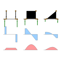
8. Beam Loading
 |
8. Beam Loading |
| Before You Begin |
This demonstration relates to bending moment (M) and vertical force (V) diagrams for various loading conditions, and should be undertaken after you have gained a basic understanding of these concepts.
|
||||
| The Screen | There are no toggles on this screen. You can control it only
by moving yellow circles with the mouse. There are V and M diagrams
for three loading conditions: |
||||
| To the left, two concentrated loads. In the center, a uniformly distributed load. To the right, a linearly distributed load. A typical illustration of
this load distribution is the fluid pressure on a dam or the wall of a
tank. |
|||||
|
|
|||||
| Manipulations | |||||
|
Each loading diagram has a base line that overhangs the reaction to the left. The length of the overhang can be regulated by moving the reaction. To the right, each base line terminates at the reaction. However, a small yellow circle partly hidden behind the circle for the reaction point can be used to lengthen the base line and create an overhang at that end as well. The easiest way to gain full access to the small circle is to move the reaction point circle toward the center of the span first. The concentrated loads can be made larger or smaller by moving the yellow circles at the tails of their vectors. The intensity of the uniformly distributed and linearly distributed loads can be changed by moving the yellow circle at the top of the load block. The portion of the span that is covered by the load in each case is controlled by moving the yellow circles at the lower corners of the load block. In none of these three examples is the self-weight of the beam considered. As you make changes in the loadings, the program automatically makes corresponding changes in the M and V diagrams below.
|
|||||
| Things to Try | |||||
|
1. Change the loads. Increase and decrease the magnitudes of the loads and watch what how your changes are reflected in the V and M diagrams. Notice especially that the M diagram is a funicular curve for the loading in every case. You can always visualize the shape of an M diagram by first visualizing the shape that a hanging string or rope would take under the given loading, then mentally inverting the shape. 2. Move the loads. Slide the yellow circles back and forth on the base line. 3. Change the overhangs. Move the loads out onto the left overhang. Move the left reaction back and forth to increase and decrease the amount of the overhang. Create a right overhang, and repeat these experiments.
|
|||||
| Specific Exercises | |||||
|
Concentrated Loads: Make the span a simple span by moving the reactions to the extreme ends of the base line. Make the two loads equal or nearly so. Then move the loads until you achieve a constant bending moment through most of the span. What does the V diagram look like in the region where the bending moment is constant? Why? Uniformly Distributed Load: Stretch the loading block at both ends until it covers the entire length of the base line. Make the two reactions the same or nearly so by moving them to the ends of the loading diagram. Then move the reactions inward until the maximum negative bending moment values are approximately equal to the maximum positive values. Repeat the experiment for a single overhang. In each case, about what percentage of the length of the main span is the length of the overhang that gives this equality of positive and negative bending moments? Now squeeze the loading block from both ends until it covers just the portion of the span between the reactions. How much larger is the bending moment for this condition than the moment for the beam with two overhangs of optimum length? Can you think of a practical use for this information? Linearly Distributed Load: Imagine the loading diagram
to be tilted up into a vertical orientation with the heaviest load intensity
at the bottom. This is the situation in a dam o r storage tank. How different
from the bending moment diagram for a uniformly distributed load is this
M diagram? |
|||||