7. Minimum Material Truss
 |
7. Minimum Material Truss |
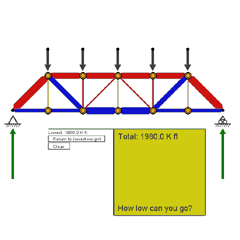
| The Screen | The Form Diagram shows the same six-panel
truss that you worked with in Demo #2. Its Force Polygon
is to the right, and numerical member forces are tabulated below. There’s
a new twist here, however: A rising and falling bar graph keeps
track of how much your truss design weighs. You can’t change
the loads, the span, or the spacing of the loads, but you can change the
form of the truss. Your task is to find a truss form that requires the
The Toggle Switches include all the ones you’re familiar with. There’s also a very handy button below, by the bar graph, that returns to the best form you’ve found. The program computes the theoretical amount of material in the truss by multiplying the amount of force in each member by the length of that member, and summing all these quantities. It is assumed in this demonstration that compression members will not buckle.
|
||||
| Designing a Minimum-Material Truss | |||||
|
1. The loading is fixed in a symmetrical pattern. Will there be any advantage in making the truss itself asymmetrical about its vertical center line? What can you predict confidently about the best form that will be found for this truss? 2. Which of the toggles will ease your task? 3. Note that although you cannot move any of the top nodes, the bottom nodes can be moved at will. 4. You already know that as a truss is made deeper, its member forces diminish. Can you produce a winning minimum-material truss just by making it very, very deep? Why or why not? Back up your answers with experimentation. 5. Be sure to try some designs in which the “vertical” members of the
truss are no longer vertical.
|
|||||
| When You’ve Finished | |||||
|
What is the logic of the form that you’ve developed? Why does it use less material than most other forms? Most trusses are subjected to a variety of loading patterns during the course of a year. You have optimized this truss for just one loading pattern. Will it be able to support other patterns as well? How will it do this? |
|||||